
Completion date: 24 Mar 2023
Description: Smart ring product design
Tags: Electronics
Tools:
Ringify, Smart Ring
Table of Contents
Background
In 2023, a few UW colleagues and I set out to design a wearable smart ring as our capstone project. While smart rings exist on the market today, they are only passive devices – they log sensor data, but offer nothing in the way of interaction. We envisioned a device focused on human-computer interaction in the same form-factor.
With our product (Ringify), users can simply tap, swipe, or press on the side of the ring with their thumb in order to launch a predefined action on their smartphone via bluetooth (examples include music controls, sending automated SMS, etc).
Demo of the ring interacting with the smartphone app
What’s Inside
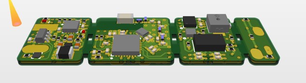
In total, the ring houses 4 custom PCBs with distinct responsibilities and a shaped Li-Po battery in the bottom cavity.
Render showing ring internals
In a finalized product, the PCBs would be in a single rigid-flex assembly. Although for cost-savings on a first-gen prototype, fly-wiring PCB tiles together was sufficient:
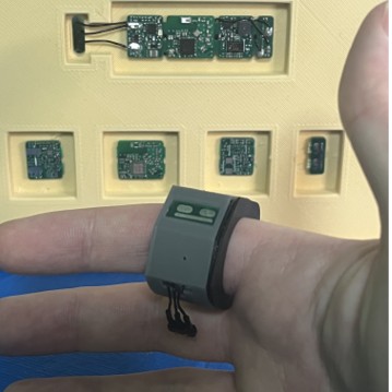 First-gen prototype of Ringify
A Few Notes on Hardware Design
I was in charge of hardware - which included all of the typical things:
- Chip Selection
- Electrical architecture
- Schematics (Altium)
- Layout (Altium)
- Assembly (planning & hands-on)
- Validation
 3d view of layout file in Altium
Feature Selection via Power Budgeting
At the end of the day, the goal of an engineering challenge like this was to optimize for the user experience, which can be over-simplified as: many features + small size + good battery life = good user experience.
The problem is that these are competing objectives. i.e.: if you increase one parameter, you’re bound to decrease another.
To tackle this balancing act, my approach was to first work with our vendors to get a list of candidate batteries, as we quickly identified that it was the bottleneck/limiting factor of the design. Then for each, I estimated the battery life for a bare-minimum system via a power budget:
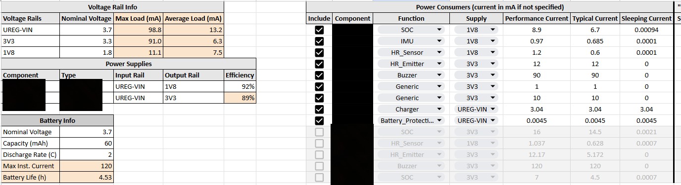 Power budgeting
I iteratively added/removed components (or features) to the power budget until an acceptable balance was achieved between feature set and battery life before locking in the parts list.
Power budgeting
I iteratively added/removed components (or features) to the power budget until an acceptable balance was achieved between feature set and battery life before locking in the parts list.
Architecture
The aforementioned approach really helped narrow our scope and eventually we developped a hardware architecture similar to what is shown below:
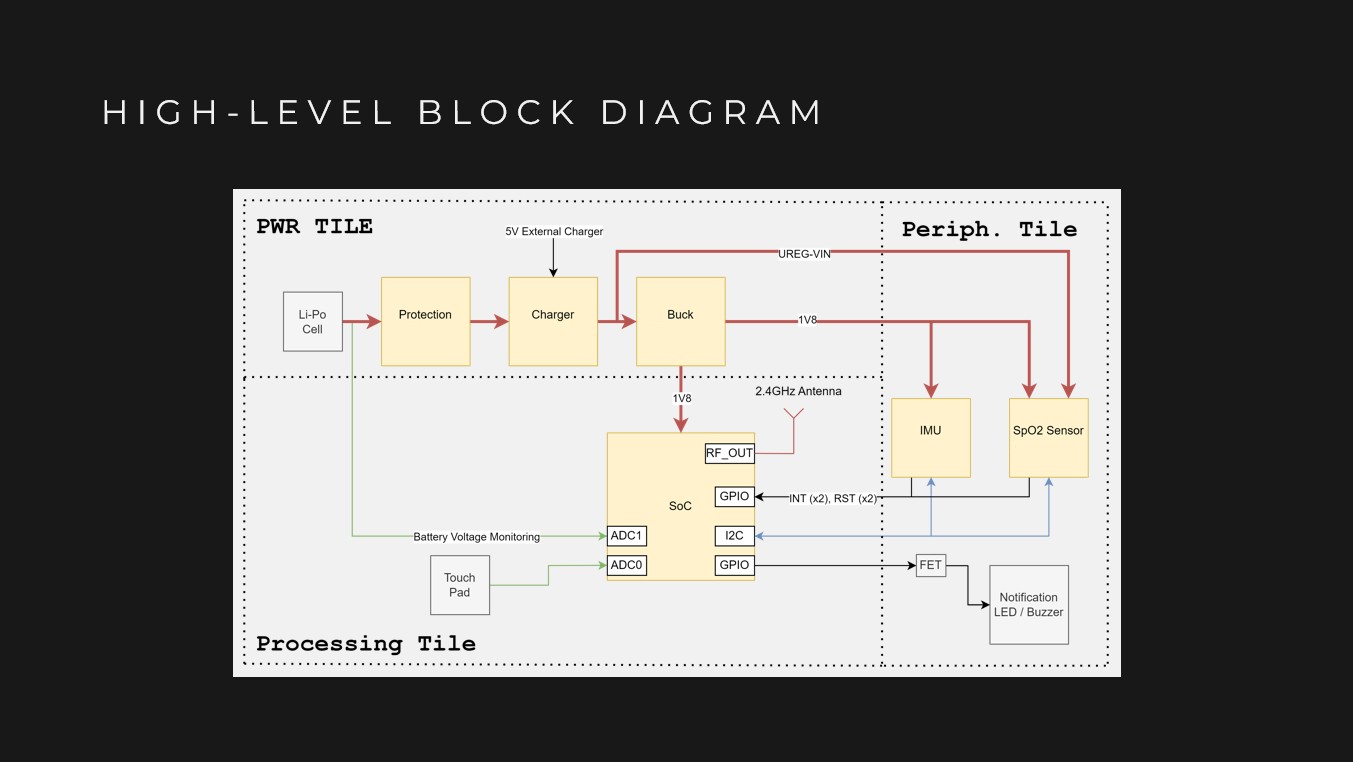 Ringify block-diagram
Power is delivered from the single-cell li-po battery through a series of protection, charging, and regulation circuits. From there, a BLE-capable System on a Chip (SoC) runs the show. The internal arm-cortex M0+ is programmed to listen for commands over BLE or from the touch pad and react accordingly. Actions include: controlling the on-board LED/buzzer, streaming data from the accelerometer/gyroscope and measuring heart-rate data.
Ringify block-diagram
Power is delivered from the single-cell li-po battery through a series of protection, charging, and regulation circuits. From there, a BLE-capable System on a Chip (SoC) runs the show. The internal arm-cortex M0+ is programmed to listen for commands over BLE or from the touch pad and react accordingly. Actions include: controlling the on-board LED/buzzer, streaming data from the accelerometer/gyroscope and measuring heart-rate data.
Basic Flashing and Debug
You’ll notice that there are no connectors on this design. This was on purpose. A dedicated port for charging/programming would improve reliability, but it would also significantly increase bulkiness (goes against our main UX objective). Instead, our board has a set of programming pads and charging pads, to which pogo-pins are pressed for charging/flashing. In the future, the ring would mechanically mate to a “dock” (TBD - To Be Designed).
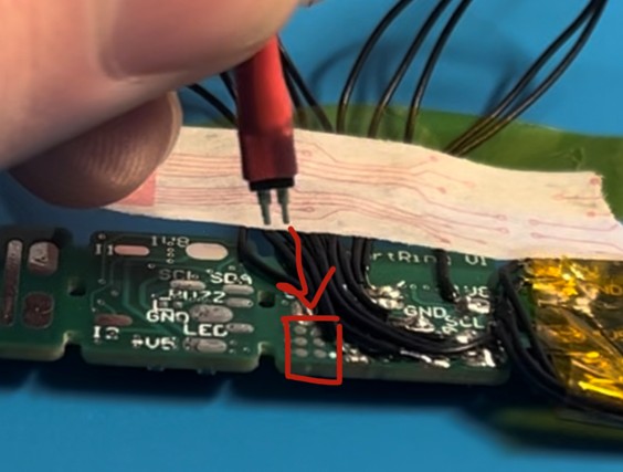 Programming pads
Over-The-Air (OTA) Updates
While developing firmware, it got annoying to hold the programmer on those pads. To resolve this, I eventually implemented an Over-The-Air (OTA) update feature. Once it was implemented, all I would do is run my Python script to transfer firmware updates from my PC to the ring via BLE. This was a productivity game-changer.
My python script implementing the client-side OTA features to flash a hex file onto the board
Assembly
As you can imagine, when funds are tight, you have to roll up your sleeves and do a lot of work in-house. The electronics assembly was no exception. Rest assured that several hours were spent in a lab to assemble, test, and rework our prototypes. The clip below outlines some notable steps in our process:
Assembly process
Achievement: out of the hundreds of tiny SMT components reworked for this project, I only lost 2-3 0402 resistors total.
Summary
Overall, Ringify represents the culmination of months of hard-work, research, and experimentation. It’s a device that packs a lot of features into a light functional design. I’m definitely proud of what we were able to accomplish and look forward to cutting down on board size in future iterations now that the prototype has been tested.
This post focuses on my contribution (hardware), but it wouldn’t have been possible to build without my colleagues in Mechatronics at UW: Kiran (Software lead), Ganesh (Mech lead), and Steven (Data lead). You can find their information on our project page: Ringify.